Why Depth of Cover Gets Measured
Every buried pipeline started life with compliant cover — federal code sets minimum burial depths at construction, varying by class location and crossing type. Then the ground starts moving. Cultivation works soil downslope, wind and water strip it, river crossings scour, ditches get regraded, and land use changes over decades. Cover that measured four feet in the construction records can be eighteen inches today, and the record will not tell you.
That is why operators measure: integrity management programs, class location changes, encroachment reviews, scour assessments after flood events, sale and acquisition due diligence, and the plain operational question of whether the plow, the excavator, or the river is closer to the pipe than anyone thinks.
The Access Problem
Traditional depth-of-cover work is done on foot — a probe, a pipe locator, or a cart-mounted radar, station by station. It works, and on accessible ground it is often the right call. But pipeline rights-of-way are not built for foot survey: they cross rivers, wetlands, standing crops, wooded draws, and ground too soft or too steep to work safely. Those inaccessible reaches are precisely where cover problems concentrate — scour lives at crossings, erosion lives on slopes.
Flying the sensor removes the access constraint. The aircraft holds a constant height above terrain, follows the centerline, and profiles reaches that a ground crew would have to skip or mobilize boats and matting to touch.
How an Airborne Cover Survey Works
- Radar along the centerline. Drone-mounted GPR flies the alignment at low altitude with RTK positioning logged per trace. Steel pipe is a strong, distinctive radar target; the pipe crown is picked from the processed section.
- Surface from LiDAR or photogrammetry. The same mobilization captures a current ground surface over the corridor.
- Cover is the difference. Surface elevation minus pipe-crown elevation, computed continuously and reported by station — not sampled every few hundred feet.
- Velocity calibrated, not assumed. Depth conversion uses signal velocity derived on site, checked against any exposed or known-depth points available, and stated in the report.
Corridor & ROW Mapping, Same Mobilization
Once the aircraft is on the right-of-way, the incremental cost of collecting more than cover data is small. The same corridor flight supports vegetation encroachment mapping, erosion and exposure monitoring, dig-site planning support for integrity digs, as-built verification of crossings, and a current orthomosaic of the entire reach. Operators who need one number often leave with a corridor dataset they use all year.
Deliverables
- Stationed depth-of-cover profile along the surveyed alignment — CSV, DXF, and plotted profile sheets
- Exception report flagging every reach below your cover threshold, with station ranges and estimated cover
- Processed radar sections with the processing chain documented, so the picks can be audited
- Corridor surface data — terrain model and imagery where flown
- GIS-ready geometry — KMZ and shapefile/DXF exports that drop into your integrity system
The Honest Limits
Radar physics does not negotiate. Wet, conductive clay attenuates signal and can put a deep pipe below usable return; large-diameter steel helps, small-diameter plastic hurts; and a radar depth is a velocity-dependent estimate, not a tape measurement. Where a reach comes back ambiguous we say so, flag it for verification digs, and never bury an uncertain pick inside a confident-looking table. Airborne cover survey is reconnaissance-grade screening over miles — it tells you where to put the pothole crew, and it is not a substitute for inline inspection.
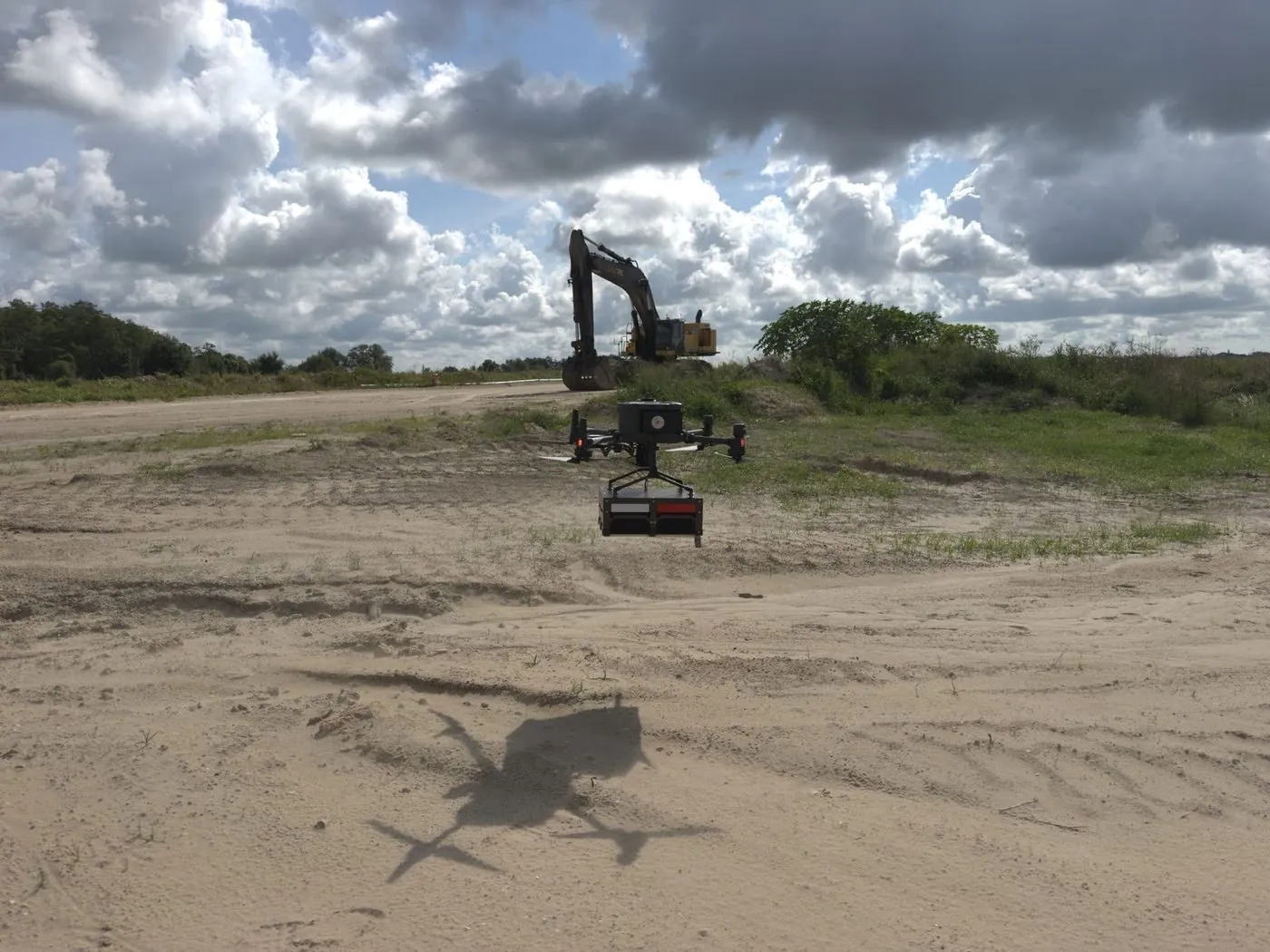
The survey platform at work: antenna slung below the aircraft, flown at a constant height above grade along the alignment.
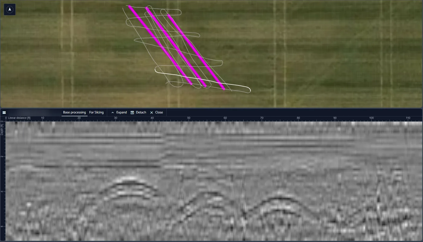
A real corridor deliverable view: RTK survey lines over the alignment (top) and the processed radargram beneath. The hyperbolic arcs near the four-foot line are buried-pipe reflections — the signature the depth picks are made from.
Northern Drone is not a licensed engineering or land surveying firm. Where sealed deliverables are required, field data is produced in partnership with licensed professionals who review and stamp the final product. Read the full licensure disclosure.